
If you have ever looked at a dead switch, a broken wire, or a device that will not turn on, you may have wondered where the fault is hiding. In many cases, the fastest way to find out is to check continuity. This simple test tells you whether electricity can move through a path without interruption.
Learning how to test continuity with multimeter is one of the most useful skills for home repair, car repair, and basic electronics. You do not need advanced knowledge. You only need the right setting on your multimeter, a safe setup, and a few careful steps.
In this guide, you will learn what continuity means, when to test it, how to read your multimeter, and how to avoid common mistakes. You will also see practical examples so the process feels clear, not confusing.
What continuity really means
Continuity means there is a complete path for electric current to travel through. If a wire is good, a fuse is intact, or a switch is closed, the path is usually continuous. If the wire is broken, the fuse is blown, or a switch is open, continuity is lost.
A multimeter checks this by sending a very small signal through the part you are testing. If the path is complete, the meter tells you. Most meters either beep or show a very low resistance reading. If the path is broken, the meter stays silent or shows a high reading.
This test is not about measuring how much power a device uses. It is about checking whether the path exists at all. That is why it is so helpful for quick troubleshooting.
When continuity testing is useful
You can use continuity testing in many everyday situations:
- Checking a damaged wire
- Testing a fuse
- Checking a switch, button, or relay contact
- Finding broken traces on a circuit board
- Confirming that a plug, cable, or connector is not open inside
One important point many beginners miss: a part can look fine outside and still be broken inside. A cable may have a clean outer cover but a cut wire inside. A fuse may look normal but still be blown. Continuity testing helps you see what the eye cannot.
What you need before you start
You do not need much equipment. In most cases, a basic digital multimeter is enough.
| Item | Why it matters |
|---|---|
| Digital multimeter | Used to test continuity and read resistance |
| Test probes | Used to touch the points you want to check |
| Power turned off | Keeps the test safe and accurate |
| Basic access to the part | Needed to reach both ends of the wire or component |
Before testing, make sure the device is unplugged or powered off. This is not just a safety habit. It also prevents false readings and possible damage to the meter.
If you are unsure about electrical safety, read the guidance from the UK Health and Safety Executive. It gives useful basic advice on electrical safety at work and at home.
How to test continuity with multimeter step by step
Here is the practical process. Follow it slowly the first few times. After that, it becomes very easy.
1. Turn off power and disconnect the circuit
This is the first rule. Power must be off before you test continuity. If you are checking a wire in a machine, unplug the machine. If you are testing part of a car circuit, remove the battery connection if needed and follow safe repair steps for that vehicle. If you are testing a household item, unplug it from the wall.
Also try to isolate the part you are testing. If other parts of the circuit are still connected, they may affect the reading. Beginners often skip this step and then get confused by strange results.
2. Set the multimeter to continuity mode
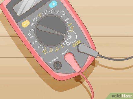
Look for the continuity symbol on your multimeter. It is often a sound wave sign, a small speaker-like icon, or a diode/continuity setting. Some meters combine continuity and diode testing on the same dial position.
Turn the dial to the continuity setting. If your meter has a beep function, it will usually beep when the probes touch a complete path.
Sometimes a meter does not have a separate continuity mode. In that case, you can use the lowest resistance setting. A low reading means continuity. Still, if your meter has a continuity mode, use that first because it is faster and easier.
3. Check that the meter works
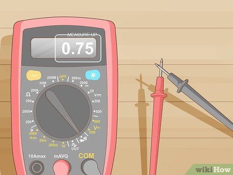
Before testing your part, touch the two probes together. A working meter should beep or show a very low resistance reading, often close to 0 ohms.
This simple step saves time. If the meter does not react when the probes touch, the problem may be the meter battery, the probe leads, or the selected mode. Do not blame the wire or fuse until you confirm the meter is working.
4. Place the probes on the two points you want to test
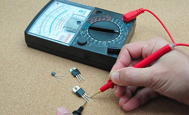
Touch one probe to one end of the path and the other probe to the opposite end. For a wire, test from one end to the other. For a fuse, touch both metal ends. For a switch, touch the two terminals.
Make sure the probe tips have good contact with clean metal. Paint, rust, dirt, and oxidation can block the connection between the probe and the part. If needed, gently clean the contact point first.
Hold the probes steady. A weak touch can cause the meter to beep on and off. That can make you think the part is bad when it is not.
5. Read the result
If the meter beeps or shows a very low resistance value, the path is continuous. If it stays silent or shows a very high reading, the path is open.
Here is the simple meaning of the result:
- Beep / low resistance: continuity is present
- No beep / high resistance: continuity is absent
Some meters beep only when resistance is very low. Others beep over a wider range. That is why the display matters too, not just the sound.
6. Test again to confirm
If the result surprises you, test it a second time. Move the probes and check again. Try both directions if the part has polarity or internal contacts. A good habit is to confirm any important result before replacing a part.
Non-obvious tip: when testing a wire harness or connector, gently wiggle the wire while watching the meter. If continuity comes and goes, the wire may be broken inside near the bend point. This kind of hidden fault is very common.
How to understand different continuity readings
Not every meter gives the same style of reading, so it helps to know what you are seeing.
Credit: wikihow.com
Beep and low number
This is the most common result. It means the path is closed. For a good wire, fuse, or closed switch, this is what you want to see.
No beep and OL or 1
Many meters show OL, 1, or another high/open signal when there is no continuity. That means the path is broken or open.
Higher than expected resistance
Sometimes a path is not fully broken, but the resistance is too high. This can happen with corroded contacts, weak connectors, or damaged wires. The meter may still beep on some models, but the reading may not be normal.
This is an important beginner mistake: not all continuity problems are full breaks. A connection can be partly damaged and still cause real trouble in a device.
Common things people test with continuity
Testing a wire
To test a wire, place one probe on one end and the other probe on the opposite end. A good wire should beep or show very low resistance. If it does not, the wire may be broken somewhere inside.
If the wire is long or part of a bundle, test from connector to connector. If you suspect a hidden break, bend the wire gently at different points while testing. Many internal breaks show up only when the cable moves.
Testing a fuse
A fuse should usually show continuity if it is good. Touch each metal end cap of the fuse. If the meter shows no continuity, the fuse is blown.
Do not rely only on looking at the fuse. Some blown fuses do not look damaged. A continuity check gives a clearer answer.
Testing a switch
A switch should usually show no continuity when off and continuity when on. That makes switches one of the best uses for a multimeter.
For example, if you test a light switch, the reading should change as you flip the switch. If it does not change, the switch may be faulty.
Testing a cable or extension cord
For a cable, test each conductor separately. Do not test the whole cable at once unless you know exactly how it is wired. A good cable may have several separate internal paths, and each one should be checked.
Another helpful habit: test from end to end, then test between different conductors to make sure there is no unwanted short. Continuity mode is mainly for open paths, but it can also help you spot accidental contact between wires.
How to avoid false readings
Continuity testing is simple, but false readings happen more often than people expect. These are the most common causes.
Credit: wikihow.com
Testing while power is still on
This is the biggest mistake. A live circuit can damage your meter and give unsafe results. Always confirm the power is off first.
Poor probe contact
If the probe does not touch clean metal, the meter may not show continuity even if the part is good. Press firmly and aim for bright, exposed metal when possible.
Testing in a connected circuit
Other parts of the circuit can create alternate paths. That may make a bad component look good, or a good component look bad. When possible, isolate the part before testing.
Dirty or corroded surfaces
A rusty terminal can block the probe and also increase resistance. Clean the surface if needed before deciding that the part is faulty.
Confusing continuity with low resistance
Continuity mode is usually a quick pass-or-fail check. It is not always enough for detailed diagnostics. A part may show continuity but still not work properly because its resistance is too high under load.
This is a second important insight many beginners miss: continuity does not always mean the part is healthy. It only tells you that a path exists. For some faults, you may need resistance testing, voltage testing, or a load test.
Safety tips that matter more than people think
Even though continuity testing is low-risk compared with other electrical tests, safety still matters.
- Always turn off power before testing.
- Do not test live mains wiring unless you are trained and using the correct method.
- Keep your fingers behind the probe guards.
- Use a meter with proper rating for the job.
- Check the probe leads for cracks or damage before use.
One practical habit is to keep one hand free when working around electrical systems. It can help reduce risk in certain situations. Still, the best habit is simple: do not test continuity on powered circuits.
How to use continuity testing in real troubleshooting
Continuity testing becomes much more useful when you use it as part of a clear process, not as a random guess.
Say a lamp does not work. You can check the bulb first. If the bulb has continuity, the filament is likely good. Next, check the switch. If the switch changes properly when turned on and off, then test the cord. This step-by-step method helps you find the fault faster than replacing parts one by one.
Here is another example. A car accessory stops working. You might test the fuse first, then the wire from the fuse to the device, then the switch or relay. By moving from source to load, you narrow the problem quickly.
That is the real value of learning how to test continuity with multimeter: it gives you a simple way to follow the path of electricity and find the break.
What to do if the meter keeps beeping when it should not
If your meter shows continuity when you do not expect it, do not assume the meter is wrong. First, think about hidden paths in the circuit.
For example, a motor winding, indicator light, or connected component may create another path that your meter can detect. This does not always mean the part you are testing is directly connected in the way you think.
Try disconnecting one side of the part and testing again. If the strange reading disappears, the circuit was affecting the result. This is why isolation matters so much.
Quick decision guide
- If the part should be closed, a beep usually means it is good.
- If the part should be open, no beep usually means it is good.
- If the reading changes when you move the wire, suspect an internal break.
- If the reading seems odd, isolate the part and test again.
How to read resistance values in continuity mode
Some meters show a number instead of only a beep. A very low number, often near 0 ohms, means a strong continuous path. A higher number means more resistance in the path.
There is no single perfect resistance number for every situation because meters and leads are not identical. Still, for simple continuity checks, the reading should be very low. If you see a noticeably higher reading, compare it with a known good part or check the meter leads first.
Tip: touch the probes together and note the reading. That is your meter’s baseline. Then compare the part to that baseline. This gives you a better feel for what “normal” looks like on your device.
Credit: sanwa-america.com
Best practices for accurate results
If you want reliable results every time, build these habits.
- Confirm the circuit is powered off.
- Test the meter by touching the probes together.
- Make sure probe tips touch clean metal.
- Isolate the part when possible.
- Repeat any result that looks strange.
These small steps prevent most beginner errors. They also save time because you will not chase a false fault.
Final thoughts
Once you understand the basics, continuity testing becomes one of the easiest and most useful checks you can do with a multimeter. It helps you find broken wires, failed fuses, bad switches, and hidden connection problems fast.
The key is to stay safe, power the circuit off, and read the meter carefully. If you follow the step-by-step process above, you will be able to test simple parts with confidence and avoid the most common mistakes.
FAQs
1. What does it mean if my multimeter does not beep during a continuity test?
If your multimeter does not beep, it usually means the circuit is open and there is no continuous path. Check that the meter is set to continuity mode, the probes are working, and the test points have good contact. If all of that is correct, the part may be broken.
2. Can I test continuity on a live circuit?
No, you should not test continuity on a live circuit. Turn the power off first. Testing a powered circuit can damage the meter, give false readings, and create a safety risk.
3. Why does my meter show continuity in both directions?
Some parts, like wires and closed switches, have no direction. They should show continuity either way. If you are testing a diode or another polarized part, it may behave differently. In that case, use the correct test mode for that component.
4. Is continuity the same as resistance?
They are related, but not the same. Continuity is a quick check that tells you whether a path exists. Resistance is a measurement of how much the path resists current. A continuity test often uses low resistance as the sign of a good path.
5. What should I do if continuity is present but the device still does not work?
If continuity is present but the device still fails, the problem may be poor contact under load, high resistance, a damaged component, or a fault somewhere else in the circuit. In that case, you may need to test voltage, load, or other components one by one.
