If you work with electronics, a small part can cause a big problem. A bad diode can stop a circuit, block current the wrong way, or make a device behave strangely. The good news is that you do not need expensive tools to check one. In many cases, a simple multimeter is enough.
Knowing how to test diode with multimeter can save time, money, and stress. It helps you find a faulty part before you replace the wrong thing. It also gives you a better idea of how the circuit should behave. With a few simple steps, you can test a diode at home or in a workshop.
This guide explains the process in a clear way. You will learn how to prepare, how to read the meter, what results are normal, and what mistakes to avoid. You will also see how diode testing changes when the diode is part of a circuit. Let’s make it simple.
What a diode does and why testing matters
A diode is a small electronic part that lets current flow in one direction and blocks it in the other. This one-way action is very important in power supplies, chargers, motors, and many other devices. If a diode fails, the whole circuit may stop working or work in a weak and unstable way.
Diodes fail in a few common ways. They may go open, which means no current passes at all. They may go short, which means current passes in both directions. They may also become weak, leaky, or damaged by heat. Some of these problems are hard to see by looking at the part, so a meter test is the best answer.
One thing beginners often miss is that not every diode has the same voltage drop. A normal silicon diode usually shows about 0.6 to 0.7 volts in forward bias. A Schottky diode may show a lower value, often around 0.2 to 0.4 volts. A light-emitting diode, or LED, can show a higher reading. So the reading must match the type of diode you are testing.
Another detail many people miss is that a good diode in a circuit may still give strange results because other parts are connected to it. That is why testing the diode outside the circuit, when possible, gives the clearest result.
What you need before you start
You do not need much equipment to test a diode properly. In most cases, a digital multimeter is enough. A good meter should have a diode test mode. This mode is better than simple resistance mode because it sends a small current through the diode and shows the forward voltage drop.
Before testing, gather the basics:
- Digital multimeter with diode test mode
- Test leads that are in good condition
- Safety glasses if you are working on live or unknown equipment
- Component information, if you know the diode type
- Needle nose pliers or soldering tools, if you need to remove the diode from a board
If your multimeter does not have diode mode, you can still use resistance mode, but the result is less accurate. Diode mode is the better choice because it is built for this job. If you want a good reference on diode behavior and symbols, a trusted source like All About Circuits can help.
Find the diode and identify the markings
Before you test, make sure you know which part is the diode. On a circuit board, a diode is usually a small black cylinder with a silver or white band on one end. Some diodes are glass, and some are tiny surface-mount parts. LEDs look different, but they are still diodes.
The band on the diode usually marks the cathode. The other side is the anode. This matters because a diode test checks current in one direction first, then the other direction. If you mix up the ends, you may think the part is bad when it is actually fine.
When possible, read the part number printed on the diode or nearby circuit board. This can help you find the expected voltage drop. It also helps you know whether the part is a normal diode, Schottky diode, zener diode, or LED. Different diode types can behave differently in a meter test.
Set the multimeter the right way
Turn the multimeter dial to diode test mode. This mode is often marked with a small diode symbol. If your meter has an auto-range function, it will choose the correct reading range on its own. If it does not, the diode mode should still work in a simple way.
Plug the black lead into the COM port. Plug the red lead into the port marked for voltage, resistance, or diode testing. On many meters, this is the same red input. Do not use the current input unless your meter manual clearly says to do so.
Some meters beep or show a tiny open-circuit symbol when the leads are not touching anything. That is normal. What matters is the reading you get when the leads touch the diode.
Check the meter before testing
It is smart to test the meter itself first. Touch the leads together. In diode mode, many meters will show a low reading or may show a connection symbol. This tells you the meter is working and the leads are making contact.
Also inspect the probes. Dirty probe tips can give false readings. If they look oxidized or bent, clean or replace them. A bad probe can make a good diode look bad.
How to test diode with multimeter in diode mode
This is the most useful method for most situations. It is fast, simple, and reliable for checking whether the diode is healthy.

Credit: fluke.com
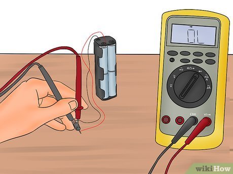
Step 1: Place the red probe on the anode
Touch the red probe to the anode side of the diode. Place the black probe on the cathode side. A good diode should allow current in this direction. Your meter should show a forward voltage reading.
For a standard silicon diode, you will often see a value around 0.5 to 0.8 volts. For a Schottky diode, the reading is usually lower. For an LED, the value may be much higher, often above 1.5 volts depending on color and type.
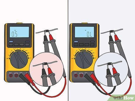
Step 2: Reverse the probes
Now switch the probes. Put red on the cathode and black on the anode. A good diode should block current in this direction. The meter should show OL, open loop, or no reading. This means the diode is not conducting the wrong way.
If your meter shows a low voltage reading in both directions, the diode may be shorted. If it shows OL in both directions, the diode may be open or not connected properly. Always check the probe contact before deciding the part is bad.
Step 3: Compare the result with the diode type
Do not judge the part only by whether it gives a reading. Compare the reading with the diode type. A zener diode may not show a normal forward behavior in the same way as a plain rectifier diode when tested in circuit. An LED may glow very faintly during testing, which is usually normal if the meter sends enough current.
This is one of the most useful beginner insights: a reading is only useful when you know what “normal” looks like for that specific diode. A “good” value for one diode type may look strange for another.
How to read the results correctly
Understanding the meter output is the real skill. The diode test does not just say good or bad. It gives clues about the exact failure.
The table below shows common results and what they usually mean:
| Meter result | What it usually means | What to do next |
|---|---|---|
| 0.5 to 0.8 V in one direction, OL in the other | Normal silicon diode | Usually good |
| Low reading in both directions | Shorted diode | Replace the diode |
| OL in both directions | Open diode or poor probe contact | Retest, then replace if confirmed |
| Very low or unstable reading | Leaky or partially damaged diode | Compare with a known good part |
| Higher than expected but still conducts one way | May be a different diode type or a weak part | Check part number and circuit context |
Two subtle points are easy to miss. First, a diode that tests fine at low meter current may still fail under load. Second, some bad diodes fail only when they heat up. If a circuit fails after warming for a few minutes, a cold meter test may not catch it. In that case, compare the diode with a known good one or test it after some heat exposure, if safe.
How to test a diode on a circuit board
Testing a diode while it is still soldered to a board can be quick, but it is not always perfect. Other parts around it can give a false path for current. That can make a good diode seem bad, or a bad diode seem okay.
Still, in many cases you can get a useful result without removing the diode. Start with the board turned off and fully disconnected from power. Then test the diode in diode mode just as you would on a loose part.
When in-circuit testing works well
In-circuit testing works best when the diode is not connected in parallel with other paths. If the surrounding circuit is simple, the result is often accurate enough to spot a failure quickly.
When you should lift one leg
If the reading is confusing, lift one leg of the diode from the board and test again. This removes the effect of nearby components. It is a common repair trick and often gives the clearest answer.
This is another beginner mistake to avoid: never trust a confusing in-circuit reading without checking the circuit layout. A resistor, capacitor, transistor, or another diode nearby can change the result. Testing one lifted leg is often the fastest way to remove doubt.
How to test different diode types
Not all diodes behave the same way. That is why it helps to know the main type before testing. Here is a simple guide.
Credit: wikihow.com
Standard rectifier diodes
These are the most common diodes in power circuits. In diode mode, they usually show a forward voltage between 0.6 and 0.8 volts. Reverse direction should show OL.
Schottky diodes
Schottky diodes have a lower forward voltage. Many show about 0.2 to 0.4 volts. They are useful in fast switching and low-loss circuits. If you expect a standard diode reading and see a lower value, it may still be normal.
Zener diodes
Zener diodes are a special case. In diode mode, they often behave like normal diodes in the forward direction. In reverse direction, they do not usually show their zener voltage unless tested with a proper power setup. So a multimeter diode test does not fully test the zener function.
LEDs
LEDs are also diodes. In diode mode, the meter may show a voltage drop and the LED may glow a little. The reading depends on color and type. If the LED is open, you may see OL in both directions. If it is shorted, it may show low readings both ways.
Testing in resistance mode when diode mode is not available
If your multimeter does not have diode mode, resistance mode can still help. But remember, the result is less precise. Resistance mode measures how much the diode resists current at the meter’s test voltage, not the forward voltage drop directly.
Set the meter to a mid or high resistance range. Test in one direction, then reverse the probes. A good diode should usually show low resistance in one direction and very high resistance in the other. The exact numbers may vary by meter and diode type.
Use this method as a backup, not as your first choice. If you can, use another multimeter with diode mode. It is much easier to trust the result when the meter is designed for diode testing.
Common mistakes that lead to wrong results
Many bad readings come from simple errors, not bad diodes. If your result looks strange, check these points first.
- Testing on a live circuit can damage the meter or give a false reading.
- Touching the wrong ends can make a good diode look reversed.
- Dirty probes can create unstable contact.
- Testing only in resistance mode can hide the real diode behavior.
- Ignoring nearby components can make an in-circuit reading misleading.
- Assuming all diodes should read the same can lead to wrong conclusions.
One more thing matters a lot: polarity. Always keep track of which side is the anode and which is the cathode. If you get this wrong, the result may still be physically correct, but your interpretation will be wrong.
What to do if the diode tests bad
If the diode is confirmed bad, replace it with the same type or an approved equivalent. Do not choose a random diode just because it fits the board. The voltage, current rating, speed, and package size all matter.
If the diode is part of a power supply, also check nearby parts. A failed diode can sometimes be a symptom of another problem, such as a shorted capacitor, bad transformer, or damaged transistor. If you replace only the diode and ignore the root cause, the new part may fail again.
If you are not sure about the replacement part, take a photo of the original diode before removal. Read its part number carefully. This small step can save you from buying the wrong component.
Practical example of a simple diode test
Imagine you have a small power adapter that does not work. You open it and find a black diode near the input section. You disconnect power, set your meter to diode mode, and place the red probe on the anode and the black probe on the cathode. The meter shows 0.62 V. Then you reverse the probes and the meter shows OL. That is a healthy result for a standard silicon diode.
Now imagine a different case. The meter shows 0.08 V in both directions. That usually means the diode is shorted. In a power supply, a shorted diode can blow a fuse or stop the supply from starting. If the meter shows OL in both directions, the diode may be open. Either way, the part needs more attention.
These simple readings tell you a lot before you spend time replacing parts. That is why learning how to test diode with multimeter is such a useful repair skill.
Credit: wikihow.com
Quick test flow you can remember
If you want a simple mental process, use this:
- Turn power off and disconnect the circuit.
- Set the meter to diode mode.
- Identify anode and cathode.
- Test in forward direction first.
- Reverse the probes and test again.
- Compare the result with the diode type.
- If the reading is unclear, lift one leg and retest.
This short flow is enough for most repair jobs. With practice, it takes only a few seconds per diode.
Final thoughts
Learning how to test diode with multimeter is one of the easiest ways to improve your basic electronics repair skill. It gives you a clear answer about whether a diode is open, shorted, or probably healthy. It also helps you avoid replacing good parts by mistake.
The key is simple: use diode mode when possible, test in both directions, and compare the reading with the type of diode you are checking. Do not forget that in-circuit testing can sometimes mislead you. When in doubt, remove one leg and test again. That small extra step often gives the truth.
FAQs
1. Can I test a diode without removing it from the circuit?
Yes, you can often test a diode while it is still on the board. This works well in simple circuits. But other parts can affect the reading, so if the result is unclear, lift one leg of the diode and test again.
2. What reading should a good diode show on a multimeter?
A standard silicon diode usually shows about 0.6 to 0.7 volts in forward direction and OL in reverse direction. Schottky diodes and LEDs may show different values, so always compare the result with the diode type.
3. What does OL mean when testing a diode?
OL usually means open loop or no continuity in that direction. For a good diode, OL in reverse direction is normal. If you see OL in both directions, the diode may be open or the probes may not be making contact.
4. Can a diode test good with a multimeter and still fail in real use?
Yes. A diode can pass a low-current meter test and still fail under heat or load. This is why a meter test is helpful, but not always the only test needed in a repair.
5. Is resistance mode good enough to test a diode?
Resistance mode can give a rough idea, but diode mode is better and more accurate. If your meter has diode mode, use it first. Use resistance mode only as a backup when diode mode is not available.
