If you want to test a wire, heater, motor, fuse, or circuit path, learning how to measure resistance with multimeter is one of the most useful skills you can have. It helps you check if a part is open, shorted, damaged, or still working as expected.
The good news is that resistance testing is not hard. You do not need advanced tools. A simple digital multimeter can give you fast answers if you use it the right way. The real skill is not just turning the dial. It is knowing what the reading means and when the reading can mislead you.
In this guide, you will learn the process step by step, along with practical tips, common mistakes, and real-world examples. By the end, you will know how to test resistance safely and read the results with confidence.
What resistance means in simple terms
Resistance is the amount of opposition a part gives to electric flow. It is measured in ohms, shown by the symbol Ω. A low resistance means electricity can pass more easily. A high resistance means the flow is harder.
When you measure resistance with a multimeter, you are checking how much a component resists current. This is useful in many situations:
- Checking a wire for breaks
- Testing a fuse
- Measuring a heating element
- Finding a bad switch or connector
- Comparing a part to its normal value
One important thing to remember is that resistance is not the same as continuity, even if both tests may seem similar. Continuity only tells you if there is a path. Resistance gives more detail about how much the path resists current.
Before you start, use the right safety habits
Testing resistance is simple, but only if the circuit is safe to measure. A multimeter in resistance mode sends a small internal voltage through the item being tested. Because of that, you should never measure resistance on a live circuit.
Here are the main safety rules:
- Turn off the power first.
- Unplug the device if possible.
- Discharge capacitors before testing.
- Remove at least one side of the component if the reading could be affected by other parts in the circuit.
- Do not measure resistance on batteries, live outlets, or energized electronics.
A useful habit is to treat resistance testing as a power-off test only. If power is still present, your reading can be wrong, and the meter can be damaged.
If you want a broader meter safety reference, the Fluke multimeter guide is a good external source.
What you need before measuring
You only need a few things to get started:
- A digital multimeter
- The item or component you want to test
- Test leads that are in good shape
- Basic access to the part, wire, or connection
If you are testing small electronic parts, it helps to have a clean work area and good light. For wire testing, label the ends if needed. For appliances, take photos before disconnecting anything. Small details like that save time later.
Know your multimeter settings
Most digital multimeters have an ohms symbol, usually Ω. This is the resistance mode. Some meters are auto-ranging, which means they choose the correct range by themselves. Others need manual range selection.
Common ranges include:
- 200 Ω or similar for very low resistance
- 2 kΩ for moderate resistance
- 20 kΩ, 200 kΩ, or higher for larger values
If your meter is auto-ranging, you can simply switch to resistance mode and start testing. If it is manual, start with a higher range, then move lower for a more precise reading.
How to measure resistance with multimeter step by step
1. Turn off power and isolate the part
Before anything else, make sure the circuit is completely off. If possible, unplug it from the wall or remove the battery. Then isolate the component you want to test.
This step is often skipped by beginners. That is a mistake. If the part is still connected to the rest of the circuit, other paths can affect the reading. You may think a resistor is bad when the real issue is another component in parallel.
2. Insert the test leads correctly
Put the black lead into the COM port. Put the red lead into the port marked for volts, ohms, or continuity. On many meters, it is the same port.
This seems basic, but it matters. If the leads are in the wrong ports, the meter may not work correctly in resistance mode.
3. Select the resistance setting
Turn the dial to the Ω symbol. If your meter has multiple ranges, choose one that is above the expected resistance.
For example:
- For a fuse or wire, start at the lowest range
- For a resistor marked 1 kΩ, start at a range above that value
- For a heating element, start with a higher range if you do not know the value
If you choose a range that is too low, the meter may show OL or overload. That usually means the resistance is higher than the selected range.
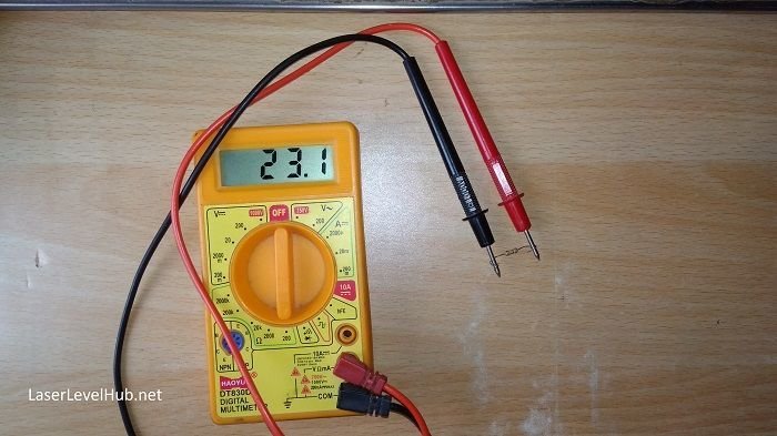
4. Check the meter leads first
Touch the two probe tips together. The meter should show a very low reading, often close to zero. This helps you confirm that the meter and leads are working.
Some meters may show 0.2 Ω, 0.4 Ω, or another small value. That is normal because the leads themselves have a little resistance. If your meter has a relative or zero function, you can use it to subtract lead resistance for more accurate low-ohm testing.
This is one of the beginner mistakes many people miss: when testing very low resistance, the resistance of the leads can become a big part of the reading. That means a wire that should read nearly zero may look slightly higher than expected.
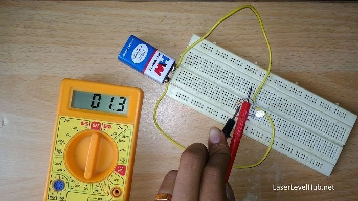
5. Place the probes on the component
Touch one probe to each end of the part you want to test. Make sure the contact is firm and clean. Bad probe contact can cause unstable numbers.
If you are testing a resistor, measure across both leads. If you are testing a fuse, touch each end of the fuse. If you are testing a wire, measure from one end to the other.
Keep your fingers away from the metal probe tips while testing. Your body can add resistance and slightly affect the reading, especially with sensitive measurements.
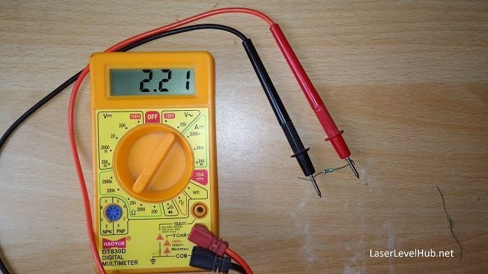
6. Read the display
The meter will show a number in ohms, kilohms, or megohms, depending on the value. For example:
- 0.5 Ω may mean a nearly direct path, such as a wire or closed switch
- 220 Ω may be a resistor or component with low resistance
- 1.0 kΩ means 1,000 ohms
- OL or 1 on some meters means open circuit or out of range
Do not read the number too quickly. Wait a second or two for the value to settle, especially if you are testing a part connected to other components.
7. Compare the reading to the expected value
This is where the test becomes useful. A reading alone does not tell the full story. You need to compare it with what the part should be.
Here is a simple guide:
| Reading | What it may mean |
|---|---|
| Very close to 0 Ω | Good continuity, wire path, closed switch, or short circuit depending on context |
| Matches the part value | Component may be healthy |
| Much higher than expected | Possible damage, loose connection, or partial break |
| OL / infinite resistance | Open circuit, broken wire, blown fuse, or failed component |
One non-obvious point many beginners miss is that a part can look physically fine and still fail electrically. A fuse may have no visible damage, but resistance testing can still show an open circuit. The meter gives the real answer, not the appearance.
How to test common parts the right way
Credit: laserlevelhub.net
Testing a resistor
A resistor should usually measure close to its printed value. If the resistor is marked 1 kΩ, a reading near that value is normal. Small differences are expected because many resistors have tolerance, such as 1%, 5%, or 10%.
If the reading is far above the rating, the resistor may be damaged. If it shows OL, it may be open. If it reads much lower than expected, there may be another path in the circuit affecting the result.
Testing a fuse
A good fuse should read very low resistance, close to 0 Ω. A blown fuse often reads OL. If the fuse has resistance that jumps around, the internal element may be cracked or weak.
For best results, remove the fuse from the holder when possible. Testing it in place can sometimes give false results if other parts are connected in parallel.
Testing a wire or cable
Place one probe on each end of the wire. A good wire usually shows almost zero resistance. Long wires may show a small value because every conductor has some resistance.
If the reading is unstable, check the probe contact points. Oxidation, dirt, or loose connections can create misleading numbers.
Testing a switch
With the switch off, it should usually show OL or very high resistance. With the switch on, it should read close to 0 Ω. If the reading stays high when the switch is on, the switch may be worn or dirty.
Testing a heating element
Heating elements often have a lower resistance than people expect. The exact value depends on the device. If the reading is OL, the element may be broken. If the reading is very different from the normal value, it may still be failing even if it looks intact.
How to measure resistance in circuit vs out of circuit
There are two ways to test resistance: in circuit and out of circuit. Both can be useful, but they do not give the same level of confidence.
Credit: laserlevelhub.net
In circuit testing
This means the part is still connected to the board or device. It is fast and convenient. However, nearby components can affect the reading.
Use in-circuit testing when:
- You want a quick check
- Removing the part is difficult
- You are comparing one section to another identical section
Out of circuit testing
This means you remove at least one leg or one end of the component from the circuit. This gives a much cleaner reading because other parts are less likely to interfere.
Use out-of-circuit testing when:
- You want the most accurate reading
- The result in circuit seems strange
- You are checking a resistor, fuse, or simple part with no easy parallel paths
A second useful insight: if a component tests “bad” in circuit, do not replace it too fast. Sometimes the part is fine, but another part connected to it is changing the reading. That is why technicians often confirm suspicious readings out of circuit.
How to choose the correct range for better results
Picking the right range helps you get a stable and useful reading. If your meter is manual, a poor range choice can make the number hard to read.
Use this simple approach:
- Start high if you do not know the expected value
- Move down for more detail when needed
- Use the lowest range only when you expect a very small resistance
For example, if you are testing a 10 kΩ resistor, a 200 Ω range is too low. A 20 kΩ range is a better choice. If you are checking a wire, a low range works better because the value is near zero.
On auto-ranging meters, this happens automatically. Still, it helps to understand the logic behind it, because it explains why the display may shift before settling.
Common mistakes when measuring resistance
Many wrong readings are not caused by a bad meter. They happen because of a small testing mistake. Here are the most common ones:
- Testing on a live circuit — This is unsafe and can ruin the reading.
- Leaving the part connected — Other components can change the result.
- Not checking the leads first — A damaged lead can make every reading unreliable.
- Poor probe contact — Rust, dirt, or loose touch points can cause false high resistance.
- Expecting exact numbers — Many parts have tolerance, so small differences are normal.
- Ignoring lead resistance on low-ohm tests — This matters a lot when testing near-zero resistance.
If you avoid these mistakes, your resistance tests will be much more dependable.
How to understand strange readings
Sometimes the meter shows a value that does not seem to make sense. Do not panic. Strange readings usually have a cause.
Reading keeps changing
This can happen if the probes are not making solid contact, the component is still in circuit, or the item is a capacitor or electronic board that needs more time to settle. Check the contact points first.
Reading is higher than expected
This may mean a partial break, corrosion, a bad connection, or a component that has drifted over time. In wires and switches, a higher reading often points to wear or oxidation.
Reading shows OL
OL means the meter sees no measurable path on that range. It can point to an open circuit, but it may also mean the selected range is too low for the part. Change the range and test again.
Reading is near zero when it should not be
This can suggest a short circuit or a component failure. It can also happen when testing in circuit and another path is bypassing the part. Try testing the component out of circuit for confirmation.
Practical examples you can use at home
Here are a few simple situations where resistance testing helps:
- Extension cord: Test each wire end to end to find breaks.
- Appliance fuse: Check whether the fuse is open.
- Light switch: Confirm whether the switch closes the circuit properly.
- Heater element: See if the element has continuity and a realistic resistance value.
- Speaker coil: Check if the coil is open or close to normal resistance.
These small checks can save time before buying replacement parts. They also help you avoid replacing something that still works.
Tips for more accurate measurements
If you want cleaner results, use these habits:
- Clean the probe tips often
- Hold the probes steadily
- Test in a quiet, dry area
- Remove the component from the circuit when possible
- Compare against a known-good part if you have one
For low-resistance parts, even a small change in contact quality can alter the reading. A steady hand and clean contact points matter more than many beginners think.
Also, do not rush. A good reading is not just the number on the screen. It is the number plus the context around it.
Credit: laserlevelhub.net
When resistance testing is not enough
Resistance testing is very useful, but it does not solve every electrical problem. Some faults only appear under load, heat, or vibration. A part may show correct resistance at room temperature and still fail when power is applied.
That is why resistance testing is often the first step, not the last step. If the problem remains unclear, you may also need voltage testing, continuity testing, or inspection under load.
Still, for many basic electrical problems, knowing how to measure resistance with multimeter gives you a fast and effective way to narrow down the issue.
Quick recap
To measure resistance safely and correctly, always turn off the power, isolate the part if you can, select the right ohms range, and read the display in context. A good reading is not only about the number itself. It is about whether the number matches the component and the situation.
With a little practice, you will be able to test wires, fuses, switches, resistors, and heating elements with confidence. The more you use the meter, the more natural the process becomes.
FAQs
1. Can I measure resistance on a live circuit?
No. Resistance testing should be done only on power-off circuits. If the circuit is live, the meter reading can be wrong and the meter may be damaged.
2. Why does my multimeter show OL when I measure resistance?
OL usually means the resistance is too high for the selected range or the circuit is open. Try a higher range first. If the result stays OL, the part may be broken or disconnected.
3. Why is my resistance reading not exact?
Many components have tolerance, so small differences are normal. Lead resistance, probe contact, and nearby parts in the circuit can also change the reading.
4. What is the difference between resistance and continuity?
Continuity tells you if a path exists. Resistance tells you how much the path resists current. Continuity is a simpler test, while resistance gives more detail.
5. Do I need to remove the component before testing resistance?
Not always, but it is often better. In-circuit testing can be affected by other parts. If the reading seems odd, remove at least one side of the component and test again.
