If a motor stops working, the problem is not always the motor itself. Sometimes the power supply is weak, a wire is broken, or a switch is bad. That is why learning how to test a motor with a multimeter is so useful. It helps you find the real fault before you buy parts or replace the whole unit.
The good news is that you do not need advanced tools. A simple multimeter can tell you a lot about a motor’s health. It can show if the windings are open, if there is a short circuit, or if the motor is drawing the wrong resistance. With the right steps, you can check many common motors safely and quickly.
In this guide, you will learn what to test, how to do it step by step, and what the results mean. You will also see common mistakes people make, so you can avoid false readings and save time.
If the motor test points to a wiring or power problem, it also helps to test the ground with a multimeter and check the battery with a multimeter before replacing parts.
What you should know before testing
Before you connect the probes, make sure you know what kind of motor you are dealing with. A multimeter can test resistance, continuity, and sometimes voltage and current. But it cannot fully prove that a motor is perfect under load. It is best used as a first test, or a fault-finding tool.
Most small motors fall into one of these groups:
- AC motors used in fans, pumps, and appliances
- DC motors used in toys, tools, and small devices
- Universal motors used in drills, mixers, and vacuum cleaners
Each type has different wiring and expected readings. Still, the basic idea is the same: check for damage, check for open circuits, and check for shorts.
One important point many beginners miss: a motor can show normal resistance and still fail when running. Heat, worn brushes, a bad bearing, or a weak capacitor can cause problems that a simple ohm test will not show. So use the multimeter as part of a full check, not the only check.
Tools and safety items you need
Before you start, gather a few basic items. This keeps the test clean and safer.
- A digital multimeter
- Screwdrivers or tools to access the motor
- Safety gloves if needed
- Insulated probe tips, if available
- Motor wiring diagram or model label, if you have it
Safety matters most. Always disconnect power before testing resistance or continuity. If the motor is part of a machine with a capacitor, discharge the capacitor first. Some capacitors can hold charge even after power is off.
If you want a general safety reference for electrical work, the OSHA electrical safety guidance is a helpful place to start.
If the motor test points to a wiring or power problem, it also helps to test the ground with a multimeter and check the battery with a multimeter before replacing parts.
Step 1: Identify the motor type and terminals
Start by looking at the motor label, wiring diagram, or device manual. You want to know how many wires or terminals the motor has. This tells you where to place the probes and what result to expect.
For example, a simple DC motor may have only two terminals. A single-phase AC motor may have start and run windings. A capacitor motor may have extra leads for the capacitor circuit. If you do not identify the terminals first, your readings may confuse you.
Also inspect the motor body. Look for burned marks, broken wires, loose connectors, melted plastic, or a smell of burnt insulation. These signs often point to an electrical fault before you even use the meter.
Why this step matters
Many people jump straight to resistance testing and then wonder why the numbers do not make sense. Knowing the motor type helps you compare the reading against a sensible range. It also helps you avoid testing the wrong pair of wires.
If the motor test points to a wiring or power problem, it also helps to test the ground with a multimeter and check the battery with a multimeter before replacing parts.
Step 2: Set your multimeter correctly
Next, set the multimeter to the right mode. For most basic motor checks, use ohms or continuity.
- Use continuity when you want a quick yes-or-no check for a break in the circuit.
- Use ohms when you want a more exact resistance reading.
If your meter has manual ranges, start on a lower or middle resistance range. If it is auto-ranging, the meter will choose for you. Make sure the probes are plugged into the correct ports, usually the black lead in COM and the red lead in the V/Ω port.
Before testing the motor, touch the two probes together. You should see a low reading or hear a beep in continuity mode. This confirms the meter is working.
What a good starting reading looks like
There is no single “perfect” resistance number for all motors. Small motors may read very low, sometimes under a few ohms. Larger motors may read more. What matters most is whether the windings are continuous and not shorted to the frame.
Beginners often make a mistake here: they expect a specific number and think any small value means failure. That is not true. Many motor windings naturally have low resistance. The pattern of readings matters more than the exact number.
If the motor test points to a wiring or power problem, it also helps to test the ground with a multimeter and check the battery with a multimeter before replacing parts.
Step 3: Test for continuity in the winding
Now test the motor windings. Place the probes across the winding terminals. If the motor has two terminals, test across them. If it has more than two, use the wiring diagram to find the correct pairs.
In continuity mode, a beep usually means the circuit is complete. In ohms mode, a low resistance reading means the winding is not open. If the display shows OL, infinite resistance, or no beep where one should exist, the winding may be broken.
Write the reading down. If the motor has several windings, compare each one. They should usually be similar if they serve the same purpose.
| Reading | What it may mean | Action |
|---|---|---|
| Low resistance | Winding is likely continuous | Keep testing other parts |
| OL / infinite | Open winding or broken wire | Inspect wiring or replace motor |
| Very different from other windings | Possible damage or partial break | Compare with specification if available |
Another useful insight: a winding can fail only when hot. If the motor works cold but stops later, the winding may open after it warms up. In that case, a room-temperature test may look normal. You may need to test again after the motor has run and warmed slightly.
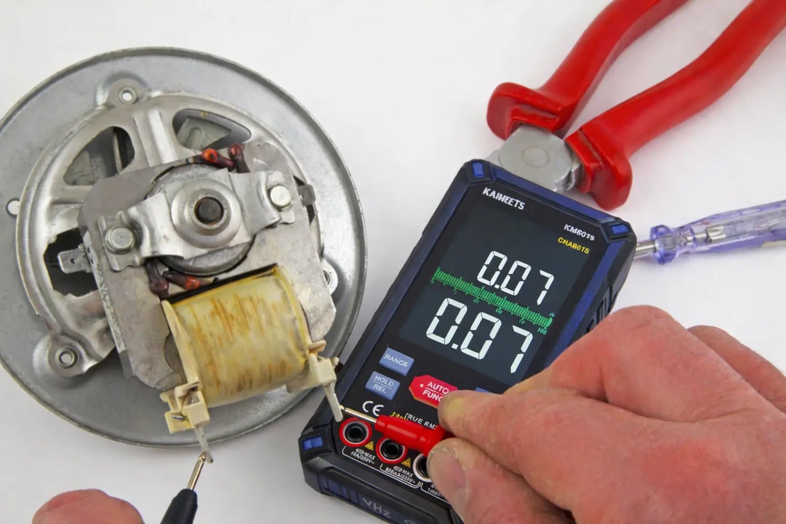
Credit: kaiweets.com
If the motor test points to a wiring or power problem, it also helps to test the ground with a multimeter and check the battery with a multimeter before replacing parts.
Step 4: Check for short to ground
This is one of the most important tests. A motor should not have continuity between the winding and the metal frame unless the design specifically allows it. A short to ground means electricity may be leaking into the body of the motor.
To test this, keep one probe on a winding terminal and place the other probe on the metal frame or housing. Repeat for each terminal. In most cases, the meter should show OL or no continuity.
If you get a low reading or hear a beep, there may be an insulation failure. That is a serious problem. It can cause tripped breakers, shock risk, or motor burn-out.
Be careful not to confuse paint, rust, or dirt with electrical contact. Use a clean metal spot on the frame. Scrape a tiny area if needed.
Why ground faults are often missed
Some beginners only test between the motor wires and forget the case. That is a mistake. A motor can still have winding continuity and yet be unsafe because part of the winding touches the frame. This is especially common in damp environments, old appliances, and motors with damaged insulation.
If the motor test points to a wiring or power problem, it also helps to test the ground with a multimeter and check the battery with a multimeter before replacing parts.
Step 5: Compare winding resistance if the motor has multiple windings
If your motor has start and run windings, or several separate coils, compare their resistance values. They should often follow a pattern. One winding may be higher than another, but a winding that is wildly different can point to damage.
For example, if two similar coils should both be low resistance and one is open, that winding is likely failed. If one winding is much lower than expected, it may be shorted.
This is where a motor label or service manual helps a lot. Some motors list expected resistance ranges. If you do not have that data, compare the readings to each other and look for major differences.
Do not force a conclusion from a single number alone. A reading of 1.8 ohms may be normal for one motor and wrong for another. Context matters.
If the motor test points to a wiring or power problem, it also helps to test the ground with a multimeter and check the battery with a multimeter before replacing parts.
Step 6: Test brushes, if the motor uses them
Many universal motors and DC motors use brushes. Worn brushes can make the motor stop, spark, or run weakly. Your multimeter can help you check the brush path.
With power off, test continuity from the brush to the commutator connection or terminal, depending on access. You are checking that the brush circuit is not open. Also inspect the brushes physically. If they are very short, cracked, or stuck, they may need replacement.
Sometimes the multimeter test looks fine, but the brush pressure is weak. That is another detail beginners miss. A brush can have continuity and still not make good contact while the motor runs.
Signs of brush trouble
- Motor runs only when tapped
- Strong sparking inside the motor
- Intermittent operation
- Burning smell near the brush area
If you see these signs, the problem may be mechanical, not just electrical.
If the motor test points to a wiring or power problem, it also helps to test the ground with a multimeter and check the battery with a multimeter before replacing parts.
Step 7: Test the capacitor if the motor uses one
Many AC motors use a start capacitor or run capacitor. If the capacitor fails, the motor may hum, start slowly, or not start at all. A multimeter can sometimes help here, depending on the model.
If your meter has capacitance mode, disconnect the capacitor and measure it directly. Compare the reading with the value printed on the part. If the meter does not have capacitance mode, you can still look for obvious faults such as a short or open condition with resistance mode, but that is less complete.
Do not test a capacitor while it is still connected to the circuit unless the manual allows it. Other parts in the circuit can distort the reading.
Simple warning sign
If a motor hums but does not start, and the windings test normal, the capacitor is often a strong suspect. This is a common case in fans, pumps, and single-phase motors.
If the motor test points to a wiring or power problem, it also helps to test the ground with a multimeter and check the battery with a multimeter before replacing parts.
Step 8: Check voltage if the motor is installed and powered
So far, most tests have been with power off. That is the safest way to check resistance and continuity. But when the motor is installed, you may also want to test voltage at the motor terminals while it is supposed to run.
Set the meter to the correct AC or DC voltage range. Then measure the supply at the motor input. If voltage is present but the motor does not run, the problem may be inside the motor or in a mechanical load. If voltage is missing, the issue may be in the switch, relay, fuse, controller, or wiring.
This step helps prevent a common mistake: blaming the motor when the real issue is upstream. A dead motor is not always a dead motor.
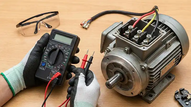
Credit: powertoolstoday.com
What to check when voltage is present
- Loose terminals
- Broken shaft or seized bearing
- Bad capacitor
- Worn brushes
- Overload device tripped
If the motor test points to a wiring or power problem, it also helps to test the ground with a multimeter and check the battery with a multimeter before replacing parts.
How to read the results the right way
The meter gives you clues, not always a final answer. A good winding reading plus a short to ground test that passes usually means the motor is electrically healthy. But the motor can still fail because of heat, mechanical drag, or control problems.
Here is a practical way to think about the results:
- Open circuit usually means a broken winding, broken wire, or bad connection.
- Short to ground usually means insulation damage.
- Normal resistance but no operation may mean a capacitor, switch, brush, or mechanical fault.
- Very low resistance compared with similar windings may point to a shorted winding.
One subtle point that helps a lot: temperature changes resistance. A motor that is warm can show slightly different readings than a cold motor. That is normal within reason. But a big shift or a reading that jumps around can point to a bad internal connection.
If the motor test points to a wiring or power problem, it also helps to test the ground with a multimeter and check the battery with a multimeter before replacing parts.
Common mistakes when testing a motor
Even a simple test can go wrong if you rush. These mistakes are easy to avoid once you know them.
- Testing with power still on — This can damage the meter and create danger.
- Forgetting to disconnect capacitors — Stored charge can shock you or affect readings.
- Testing the wrong terminals — This gives confusing results and wastes time.
- Using the wrong meter setting — Ohms mode and voltage mode are not the same.
- Assuming one reading proves everything — A motor can still have hidden faults.
Also, do not test through dirty connectors if you can avoid it. Corrosion can create false resistance. Clean contacts often give more accurate results.
If the motor test points to a wiring or power problem, it also helps to test the ground with a multimeter and check the battery with a multimeter before replacing parts.
Practical example: checking a small fan motor
Imagine a fan motor that does not start. You first unplug the fan and open the housing. You see two motor wires and a small capacitor. The motor body looks clean, with no burn marks.
First, you set the meter to ohms and measure across the motor leads. You get a low reading, not OL. That means the winding is not open. Next, you check each motor lead to the frame. The meter shows no continuity. That is a good sign.
Then you test the capacitor with capacitance mode and find it is far below its rated value. In this case, the motor itself may be fine, and the capacitor is likely the main problem. That is a simple example of how a multimeter helps you avoid replacing the wrong part.
If the motor test points to a wiring or power problem, it also helps to test the ground with a multimeter and check the battery with a multimeter before replacing parts.
Practical example: checking a drill motor
A drill motor often uses brushes and a commutator. If the drill stops working, start by checking the cord and switch for voltage. If power reaches the motor, then test the armature and brush continuity.
If the brushes are worn down to a very short length, they may not touch well. The meter might still show continuity when you test the brush path, but the motor can fail under movement and vibration. Here, the physical inspection is just as important as the electrical test.
This is another non-obvious lesson: a motor problem is often a mix of electrical and mechanical issues. A multimeter tells only part of the story.
If the motor test points to a wiring or power problem, it also helps to test the ground with a multimeter and check the battery with a multimeter before replacing parts.
When the motor should be replaced
Sometimes testing will show a clear failure. Replacement may be the best choice if:
- The winding is open
- The winding is shorted to the frame
- Several windings have abnormal readings
- The motor has visible burn damage
- The motor is seized and not worth repair
If the motor is expensive or hard to find, you may still inspect deeper for repairable parts like brushes, capacitors, or loose connections. But for many small sealed motors, replacement is faster and safer.
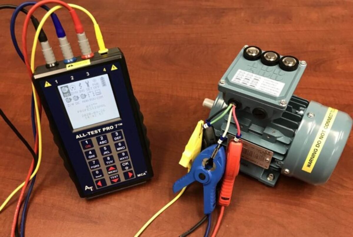
Credit: storables.com
If the motor test points to a wiring or power problem, it also helps to test the ground with a multimeter and check the battery with a multimeter before replacing parts.
Quick checklist for reliable testing
Use this simple flow when you are testing a motor:
- Disconnect power
- Discharge capacitors
- Identify the motor type and terminals
- Set the multimeter to continuity or ohms
- Test winding continuity
- Test each terminal to the frame for shorts
- Compare readings across similar windings
- Check brushes, capacitor, and supply voltage if needed
Keeping this order helps you avoid random testing and makes fault-finding much faster.
If the motor test points to a wiring or power problem, it also helps to test the ground with a multimeter and check the battery with a multimeter before replacing parts.
Conclusion
Learning how to test a motor with a multimeter is one of the best skills you can have for basic electrical repair. It helps you find open windings, ground faults, bad connections, and some capacitor problems without guessing. More important, it helps you decide whether the motor is truly bad or if the issue is somewhere else in the circuit.
Remember the big idea: the meter gives you evidence, not magic. Combine the readings with visual inspection and a little logic. That is how you get clear answers and avoid replacing good parts.
If the motor test points to a wiring or power problem, it also helps to test the ground with a multimeter and check the battery with a multimeter before replacing parts.
FAQs
1. Can a multimeter tell me if a motor is completely good?
Not completely. A multimeter can show continuity, resistance, and short circuits, but it cannot always prove how the motor behaves under full load. It is a strong first test, not a full performance test.
2. What setting should I use to test a motor?
Use continuity or ohms mode for most off-power checks. If you want to measure supply voltage while the motor is powered, switch to AC or DC voltage depending on the motor type.
3. Why does my motor show continuity but still not work?
The winding may be fine, but the fault could be in the capacitor, brushes, switch, bearing, or power supply. A motor can pass a basic resistance test and still fail in real use.
4. Should I test the motor while it is connected to the circuit?
For resistance and continuity tests, no. Disconnect the motor first. Testing in-circuit can give false readings because other components affect the result.
5. What does OL mean when testing a motor?
OL usually means open line or infinite resistance. In motor testing, it often points to a broken winding, broken wire, or a bad connection. If you see OL where you expect continuity, that is a warning sign.
